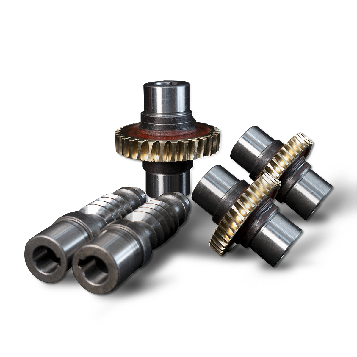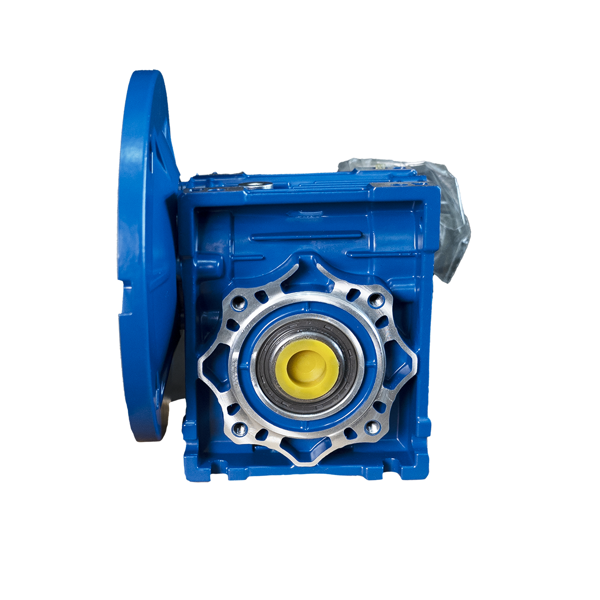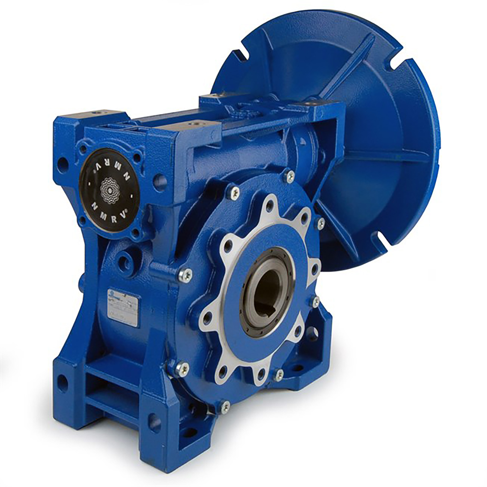
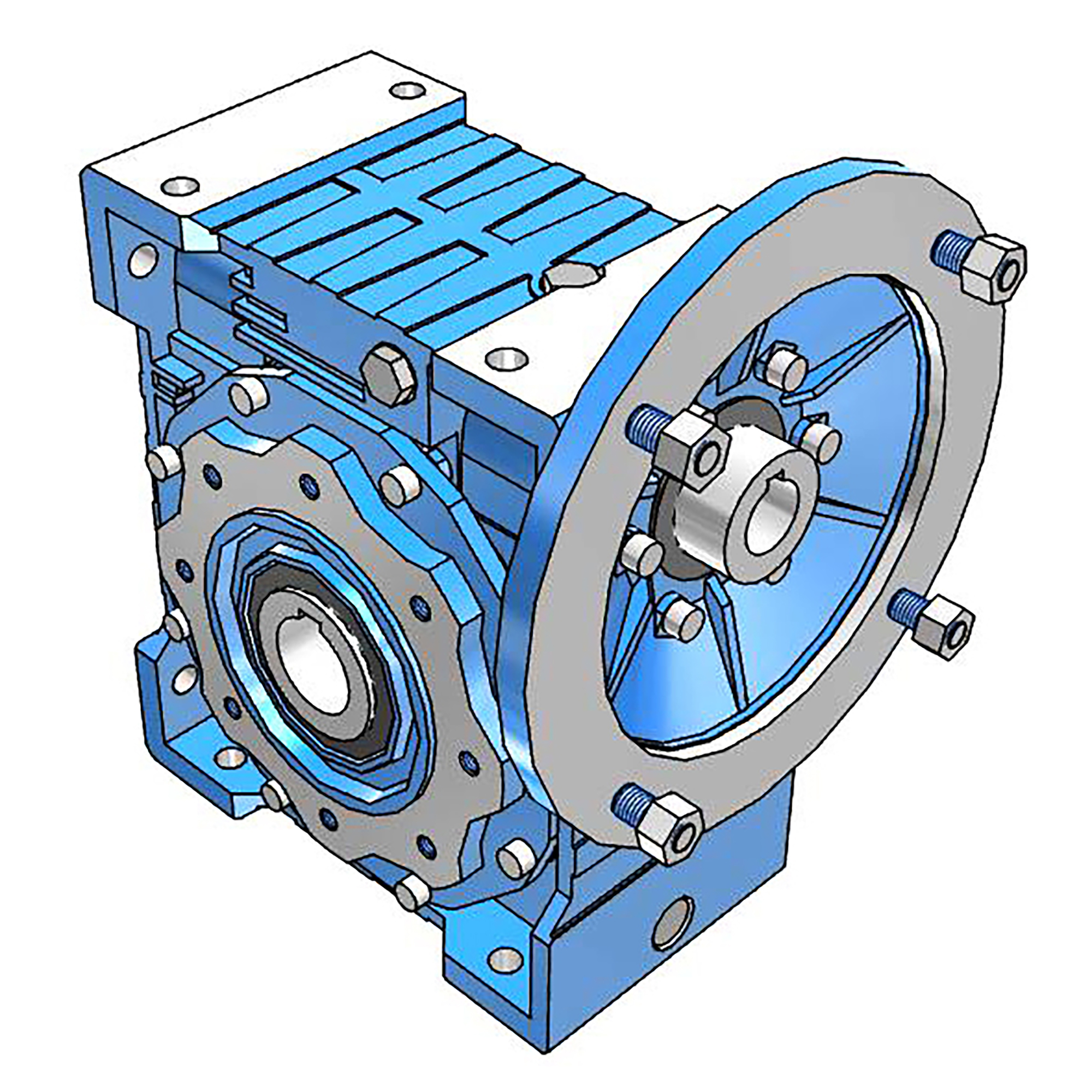

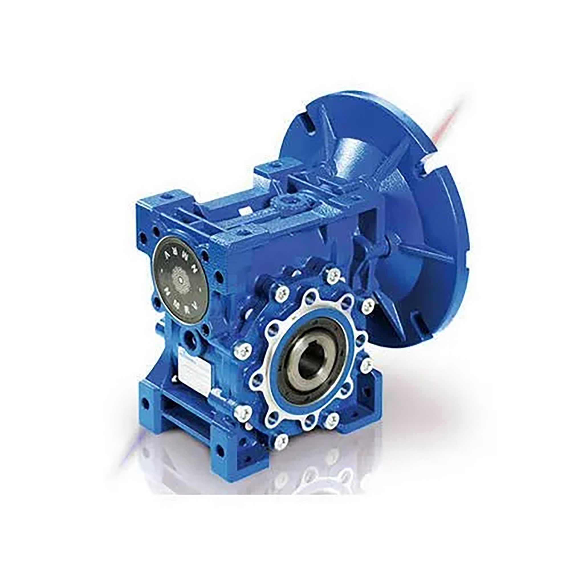
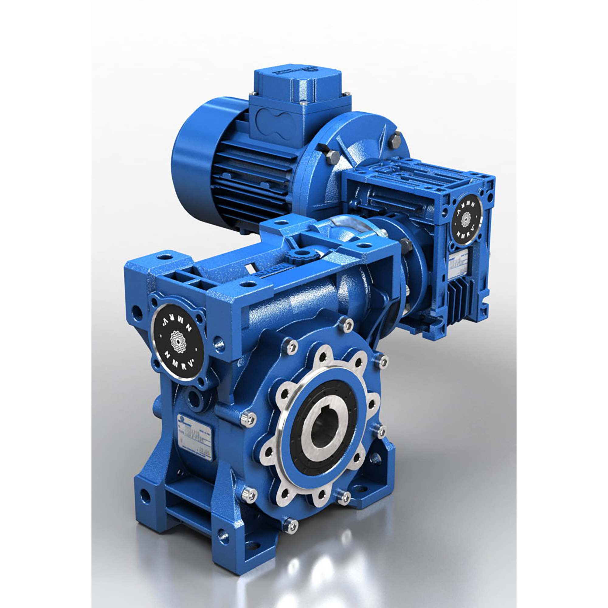


NMRV and NMRV POWER worm gear reducers currently represent the most advanced solution to market requirements in terms of efficiency and flexibility. The new NMRV Power series, also available as compact integral helical/worm option, has been designed with a view to modularity: low number of basic models can be applied to a wide range of power ratings guaranteeing top performance and reduction ratios from 5 to 1000.
For correctly selecting a gear reducer or geared motor, several essential pieces of data are required:
1. The rotational input speed to the gear reducer (n1) and the rotational output speed (n2). Through these two values it
is possible to calculate the reduction ratio (i) of the gear reducer using the following formula: i=n1/n2
2. The torque required by the application (Mr2).
The geared motor or gear reducer can be selected once this data is known.
This guide helps you to select the right product in just a few steps:
Geared motor selection
1. Determine the application’s actual service factor (s.f.). This parameter depends on the type of load of the powered
machine, the number of starts per hour and the hours of operation (refer to the “Service factor” paragraph).
2. Calculate the input power Pr1 using the required torque value Mr2, the speed n2 and dynamic efficiency value. Pr1=
(Mr2*n2)/(9550*ηd). The dynamic efficiency value depends on the type of gear reducer and on the number of gear
reduction stages. (To calculate the efficiency value see its page).
3. Consult the geared motor performance tables and identify a normalised power value Pn1 exceeding the required
power Pr1
, such that: Pn1≥Pr1
4. Once the suitable nominal power has been identified, select the geared motor capable of generating the rotational
speed closest to the desired n2 value and with service factor s.f. greater or equal to that required by the application.
In the geared motor selection tables the combinations include 2-pole, 4-pole and 6-pole motors powered at 50Hz.
Gear reducer selection
1. Determine the application’s service factor (s.f.) (consult to the “Service factor” paragraph on its page) .
2. Calculate the reduction ratio i from the requested output speed n2 and from the input speed n1. i=n1/n2
3. Calculate the torque Mc2 for selecting the gear reducer through the torque required by the application Mr2 and the
service factor s.f.: Mc2=Mr2*(f.s.)
4. Consult the Gear Reducer Performance tables looking for the reducer that, with the reduction ratio closer to the
calculated one, has a nominal torque Mn2 so that: Mn2≥Mc2
Checks
Once the gear reducer or geared motor has been selected, the following checks should be performed:
A. Maximum torque
Generally, the maximum torque (peak instantaneous load) that can be applied to the gear reducer must not exceed 200%
of the nominal torque Mn2 (ATEX – M2max).
B. Radial loads
1. Verify that the radial loads acting on the input and/or output shafts are within with the values indicated in the catalogue.
If they exceed these values, increase the size of the gear reducer or modify the external load capacity. During the
checking phase, it is important to remember that the values indicated in the catalogue refer to loads acting on the midpoint of the shaft protrusion, therefore, if the load is applied to a different position, appropriate formulas must be used to
calculate the admissible load in the desired position (refer to the “Radial loads” paragraph).
2. If accessory output shafts are present, make sure that the applied load is compatible with shaft size. If help is needed:
contact MOTOVARIO TECHNICAL SERVICE.
C. If an electric motor is going to be fitted to the selected gear reducer, check for its applicability by referring to the
configuration table (see paragraph “Motor flange availability”). From IEC 180 motors, verify if necessary to support
the motor with feet. In case of need please contact MOTOVARIO TECHNICAL SERVICE
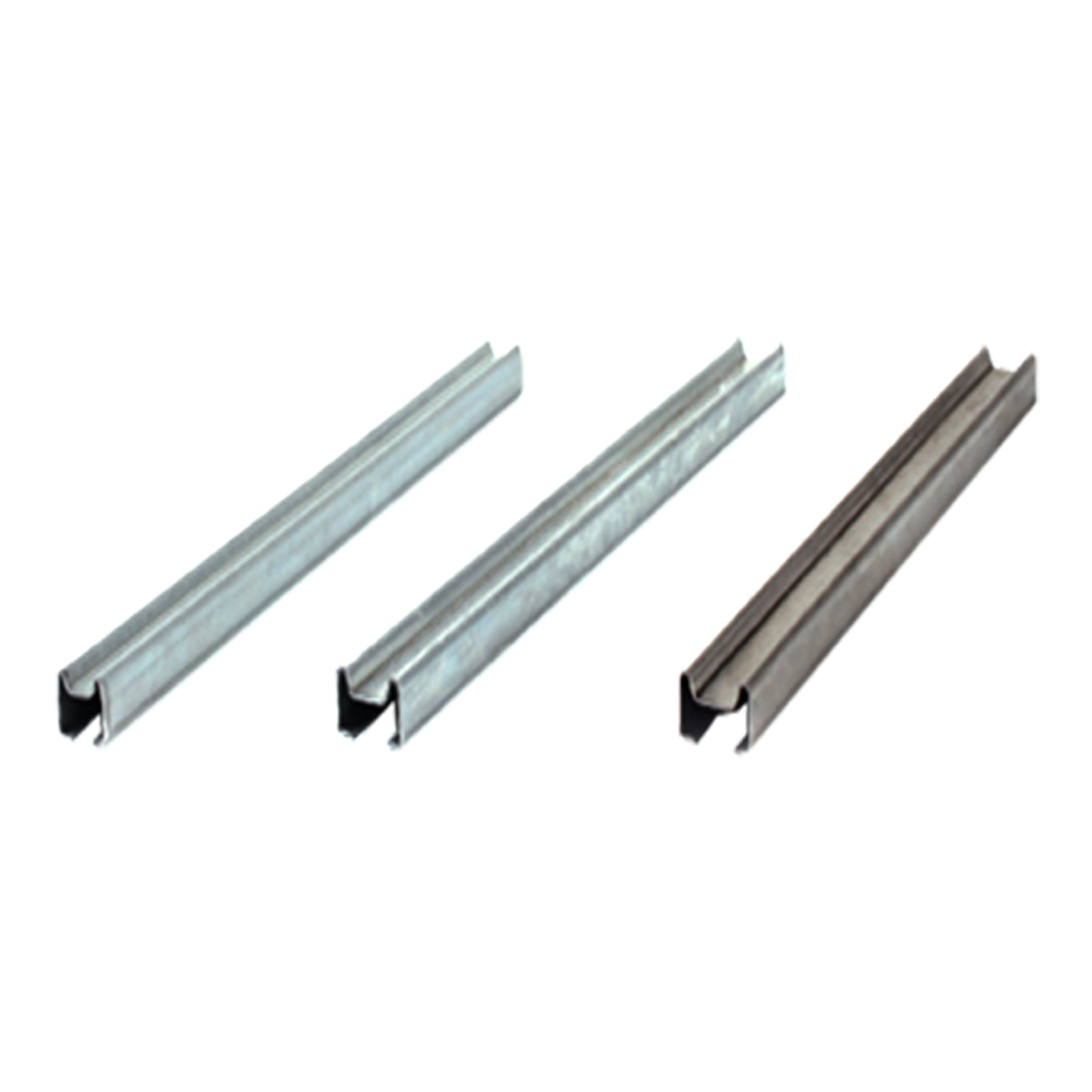
Motovario products are supplied with the following surface treatment features:
Die-cast aluminium alloy cases for gears (sizes 025-110)
Die-cast materials undergo the following surface cleaning operations:
De-burring by means of a mechanically operated shearing system.
Accurate shot-peening.
Painting.
Washing and passivation.
Grey-coloured cast-iron cases for gears (sizes 130-150)
Die-cast materials are always painted.
Painting specifications:
Orange-peel blue epoxy-polyester RAL 5010. Polyester resin based heat-hardening powders, altered with epoxy
resins.
Mechanical properties
Tests carried out onto degreased Unichim white lattens (film thickness: 60 microns) comply with the following
specifications: adherence (ISO2409).
Heat resistance
24 HOURS AT 150°C.
Corrosion strength
ASTM B 117/97 salt fog from 100 to 500 hours depending on the support’s preliminary treatment.
Performance:
Loading capacity in accordance with: ISO 14521, DIN 3996, BS 721, AGMA 6034, ISO 6336, DIN 3990, DIN 743, ISO281